Whirlpool Range Surface Element Wiring Diagram
Bf31 Whirlpool Double Oven Wiring Diagram Wiring Resources

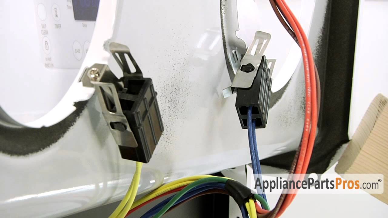
Wiring Diagram For Whirlpool Dryer

Maytag Wall Oven Wiring Diagram Wiring Diagram

Range Repair Fixitnow Com Samurai Appliance Repair Man Page 2

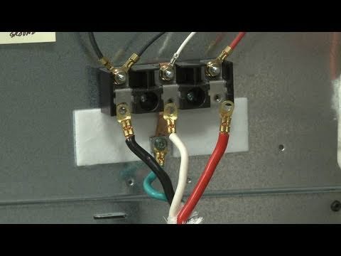
Whirlpool Range 8 Surface Element Replacement W10169799 Youtube
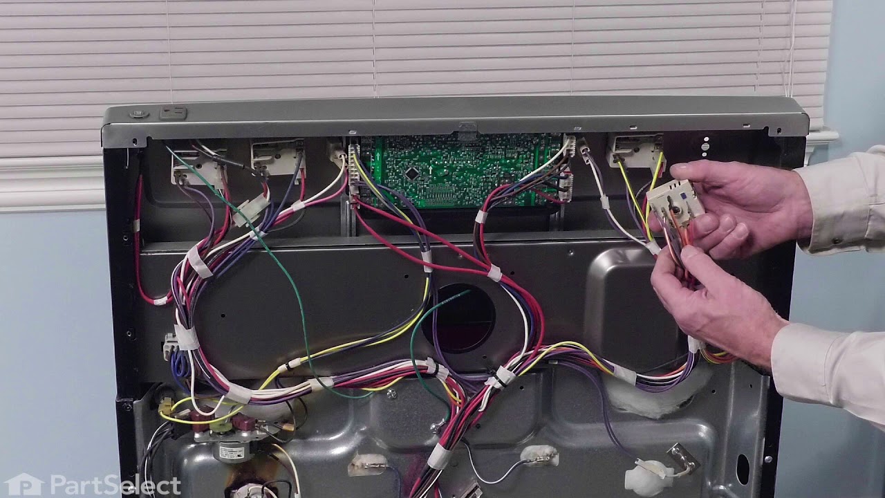
How To Oven Block Wiring Harness Youtube

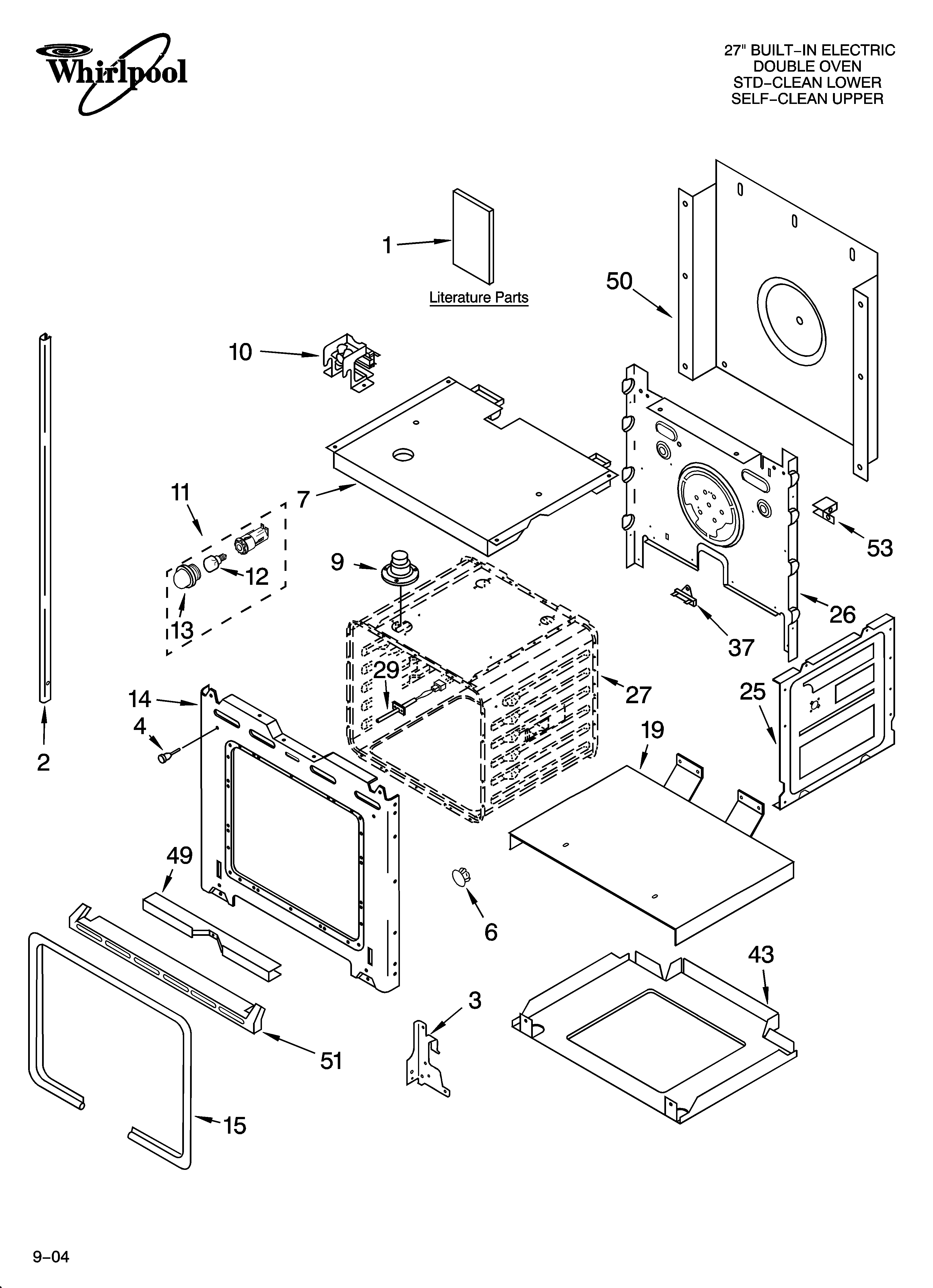
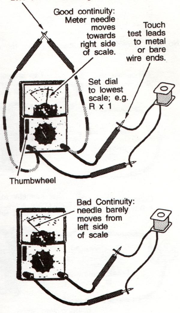
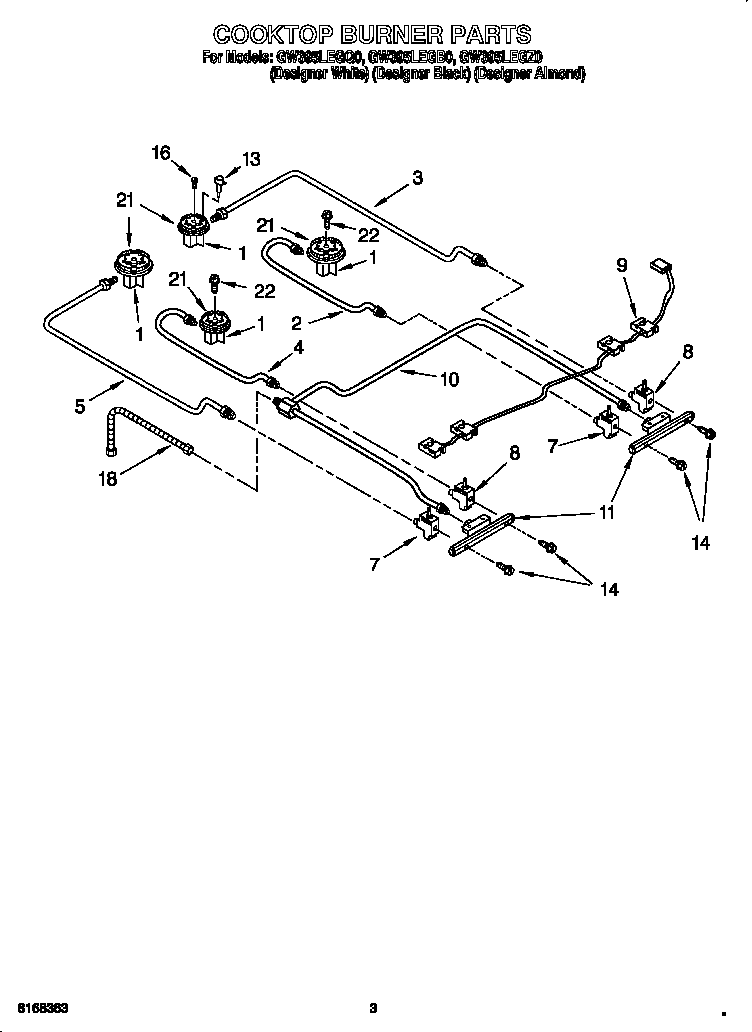
The diagram s below can help you find the right part.
Whirlpool range surface element wiring diagram. Our factory certified parts provide you with a promise only whirlpool brand can make that through our safe and genuine quality replacement parts we will care for your appliance like you care for your home every day. It s time for a wiring diagram. A ul listed conduit connector must be provided at each end of the power supply cable at the range and at the junction box. The range can be moved if servicing is ever necessary.
This whirlpool kitchenaid maytag made range infinite switch replaces the following older part numbers on whirlpool maytag kitchenaid jenn air amana magic chef admiral norge roper sears. Here are the repair parts and diagrams for your whirlpool wfc310s0ew0 electric range. Whirlpool duet heating element wiring diagram wiring diagram is a simplified adequate pictorial representation of an electrical circuit it shows the components of the circuit as simplified shapes and the aptitude and signal contacts with the devices. Sometimes life requires a little maintenance.
When your appliance does too use replacement parts designed specifically for your needs. The most common reasons for replacing the surface element switch are. Or let s say the electric oven comes on but the self clean function doesn t work. Wire sizes and connections must conform with the rating of the range 40 amps.
The wiring diagram is located on the underside of the storage. Let s say that you have power to the surface units but none to either the bake or broil element. Downloading manuals is also a convenient way of obtaining a back up in case your original document goes missing. Find the wiring diagram for your machine as described in chapter 3.
This video provides step by step repair instructions for replacing the surface element switch on a whirlpool electric range. If you d like help we invite you to call our customer service number at the top of the page or click chat. California 19410 business ctr dr. Cleveland tn 37311 1 877 477 7278.
Typical gas range wiring diagram typical gas range wiring diagram k e t ez 100 ez 150 controls timer if equipped oven control oven temp sensor p1 6 p1 7 p3 1 p2 1 surface burner ignitor switches manual oven light switch if equipped p1 1 door light sw. P1 5 transformer p1 3 latch solenoid latch solenoid relay.
Whirlpool Range Repair How To Replace The Infinite Switch

24 Wiring Diagram For Electric Stove Electric Stove Electric
Electric Range Repair Topics Appliance Aid

Solved Infinite Switch Sparking Fixya
Whirlpool Range Wire Plugs And Connectors Replacement Parts
Whirlpool Dryer No Heat Repair Guide
How To Ge Infinite Control Switch Wb24t10119 Youtube

Whirlpool Oven Manual Oven Relay

Whirlpool Range Replace Dual Surface Element Switch W10434452

W11120791 Whirlpool Range Surface Element Switch Parts Dr
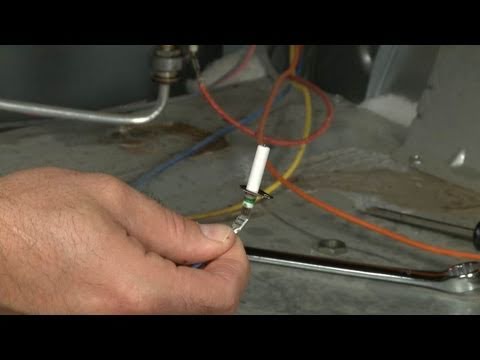
Kenmore Gas Range Burner Spark Electrode Replacement 8523793

Wiring Diagram For Ge Stove Burners Wiring Diagram
Whirlpool Gw395legz0 Gas Range Timer Stove Clocks And Appliance