Johnson Controls Aquastat Wiring Diagram
Installation And Service Manuals For Heating Heat Pump And Air

Dv 7442 Johnson Controls Aquastat Wiring Diagram Wiring Diagram
Https Cgproducts Johnsoncontrols Com Met Pdf 241135300001 Pdf

New Wiring Diagram For Ge Electric Motor Diagram Diagramsample
Https Cgproducts Johnsoncontrols Com Met Pdf 2476643043 Pdf X 69 X 69

17 New Johnson Controls A419 Wiring Diagram

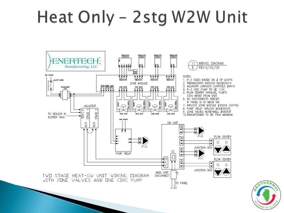
Consult the typical wiring diagrams figures 4 and 5 for proper wiring and terminal designations.
Johnson controls aquastat wiring diagram. Typical wiring diagram for a350a b powered by an external 10 va. It shows the components of the circuit as streamlined forms and the power and also signal links in between the tools. A350a b s350a d350 sensor load load l l 24 vac 1 1 2 2 24v com vdc sen note. They feature a lockable front panel touchpad for setup and adjustment and an lcd for viewing the temperature and status of other functions.
The sensor may be removed and replaced with any compatible johnson controls a99 temperature sensor or the wire leads on the sensor may be extended. Collection of johnson outboard ignition switch wiring diagram. The a419 series controls are single stage electronic temperature controls with a single pole double throw spdt output relay. The a19d series controls are designed primarily for fluid piping applications and include two.
The a19d series controls are designed primarily for fluid piping applications and include two adjustable mounting straps for mounting the control directly to a pipe. A19d series surface mounted temperature controls catalog page a19dac a19daf description the a19d series surface mounted temperature controls are reliable durable on off temperature controls with line voltage single pole double throw spdt switches. For applications at conditions beyond these specifications consult the local johnson controls office. However variations can exist such as between remote control and tiller models.
Please verify your wiring before doing any work. It shows the parts of the circuit as streamlined shapes and the power and also signal links in between the gadgets. A wiring diagram is a streamlined conventional photographic representation of an electric circuit. The performance specifications are nominal and conform to acceptable industry standards.
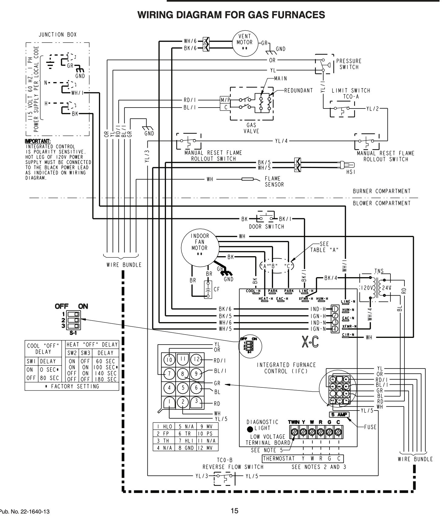
A wiring diagram is a simplified standard pictorial representation of an electrical circuit. Nortek global hvac reznor does not endorse any field changes to factory wiring schemes. See the mounting and wiring sections for additional guidelines and restrictions when mounting and wiring the control. Outboard wiring diagrams these diagrams are accurate to the best of our knowledge.
Each a419 control includes a johnson controls penn a99 temperature sensor. Collection of evinrude ignition switch wiring diagram. This material is for professional use only and is intended to be used only as reference material by licensed contractors when installing or servicing reznor equipment.

New Wiring Diagram For Solid Fuel Central Heating System

Johnston Controls A419 Digital Aquastat Sunpump
Product Documentation Johnson Controls
Https Www Titus Hvac Com File 12002 24 10143 1221 20rev 20a Frbii 20iom Pdf
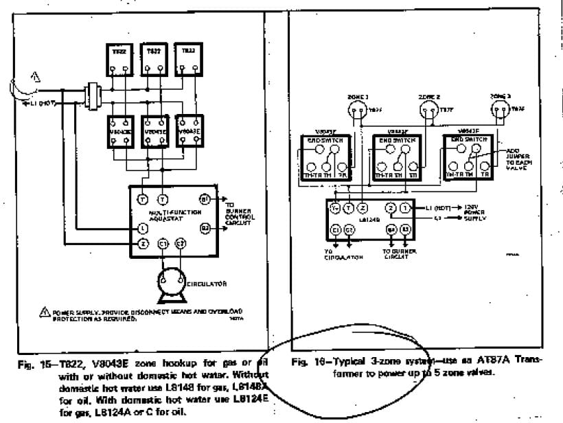
Zone Valve Wiring Manuals Installation Instructions Guide To
Https Www Enviro Tec Com Partsbook Enviro Tec Parts Book Pdf

Pin On Hvac Business And Industrial

Troubleshooting Intermittent Ignition
Http Cgproducts Johnsoncontrols Com Yorkdoc 146 00 Nom8 Pdf

Refrigerator Thermostat Connection And Full Electric Wiring

58o58o Diagram Schematic 12v Wiring Diagram For Trailer Full Hd

E350 Vent Vacuum Supply Canister Location Ford Truck Enthusiasts

New Wiring Diagram For Ac To Furnace Motores Cadetes